Description
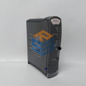
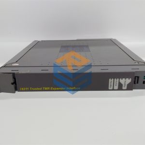
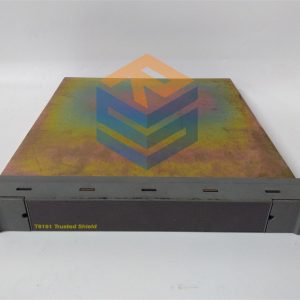
The TMR Expander Interface is a fault tolerant design based on TMR architecture arranged in a lockstep configuration. Figure 1 shows, in simplified terms, the basic structure of the TMR Expander
Interface.
The module has three main fault containment regions (FCR A, B and C). Each of the main FCRs
contains interfaces to the Expander Bus and Inter-Module Bus (IMB), an active/standby interface to the
other TMR Expander Interface in the chassis, control logic, communications transceivers and power
supplies.
Communication between the module and the TMR Processor is via the IMB on the backplane of the
Controller Chassis. The IMB provides fault tolerance and high bandwidth communications between the
Interface Modules and the TMR Processor. All transactions are voted, localising faults to the IMB
should they occur.
Communication between the Interface Module and the TMR Expander Processor in the Expander
Chassis is via the Expander Bus. The Expander Bus is triplicated, point-to-point architecture. Each
channel of the Expander Bus comprises separate command and response media. Voting is provided at
the Expander Bus Interface to ensure that cable faults are tolerated, and the remainder of the
Expander Processor operates in a fully triplicated mode, even in case of cable faults occurring.
A fourth FCR (FCR D) provides the non-critical monitoring and display functions and is also part of the
inter-FCR Byzantine voting structure.
Isolation is provided between FCRs wherever interfaces are required, to ensure that faults can not
propagate between them.
The Expander Interface Modules may reside in any of the I/O slots within the Controller Chassis. The
modules are installed in pairs with the left-hand module occupying an odd numbered slot. The
Expander Interface must NOT be installed in these other module locations, as this may cause
damage to the module.
The two Interface slots must be interconnected using the Expander Interface Adaptor Unit T8312.
The Expander Interface Modules are connected to the Expander Processor Modules by the Expander
Interface Hot Link Cable TC-301 via the TrustedTM Expander Interface Adaptor Unit T8312.
The connection to remote Expander Chassis is via the TrustedTM Fibre Optic Tx/Rx Unit using the
Expander Interface Adaptor to Fibre Tx/Rx Unit (Remote Expanders) Cable TC-302.
2.2. Module Insertion and Removal
CAUTION:
THE MODULE CONTAINS STATIC SENSITIVE PARTS. STATIC HANDLING PRECAUTIONS MUST
BE OBSERVED. SPECIFICALLY ENSURE THAT EXPOSED CONNECTOR PINS ARE NOT
TOUCHED. UNDER NO CIRCUMSTANCES SHOULD THE MODULE HOUSING BE REMOVED.
Before installation, visually inspect the module for damage. Ensure that the module housing appears
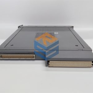
undamaged and inspect the I/O connector at the back of the module for bent pins. If the module
appears damaged or any pins are bent, do not install the module. Do not try to straighten bent pins.
Return the module for replacement.
Ensure that the module is of the correct type.
Record the module type, revision and serial number of the module before installation.
If the module is to reside in a new chassis, or the system is being configured for the first time, ensure
that the chassis address has been set correctly before installing the modules. See Controller Chassis
Product Description (PD-8100) for further details.
To install the module:
1. Ensure that the cable assembly is correctly located.
2. Release the ejector tabs on the module using the release key. Ensure that the ejector tabs
are fully open.
3. Holding the ejectors, carefully insert the module into the intended slot.
4. Push the module fully home but pressing on the top and bottom of the module fascia.
5. Close the module ejectors, ensuring that they click into their locked position.
All prices listed on the official website are subject to confirmation by contact: Wu Jiedong (manager).
Our product: brand new original packaging
Our warranty: All new or repaired parts have a 12 month warranty period beginning
Our payment: 100% telegraphic transfer of inventory items before shipment, conditions can be proposed!
If you have any downtime spare parts that you cannot find, please feel free to call or use email to contact me. If there are issues that the product cannot solve, please contact me. Product prices can be negotiated. Please do not consider contacting me!


