Description
Description
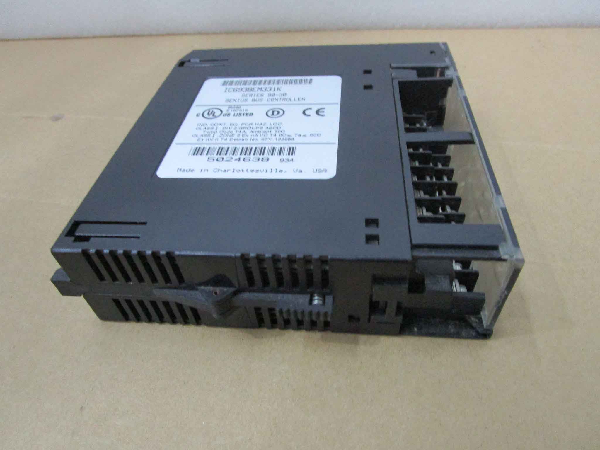
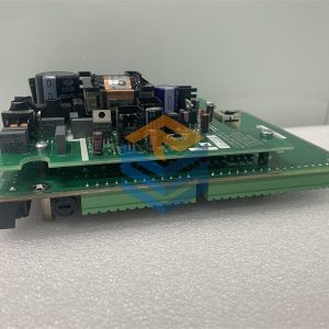
I/O Terminal Blocks are generic wiring bases that provide
module mounting, backplane communications, and terminals
for user connections. Two modules can be installed on one
terminal block. Modules screw onto the terminal block for
vibration resistance. Modules can be removed without
disturbing field wiring.
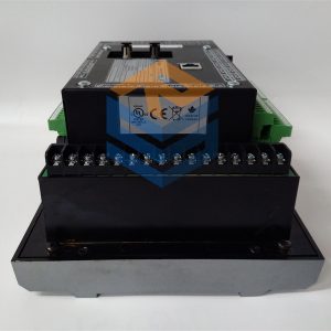
The I/O Terminal Block with barrier terminals (catalog
number IC670CHS001) has 37 terminals. The A and B
terminals are typically used for power connections to the
terminal block. The rest of the terminals are individual
terminals used for I/O wiring.
Each terminal on an I/O Terminal Block or Auxiliary Terminal
Block with Barrier Terminals accommodates up to two AWG
#14 (2.1 mm2) through AWG #22 (0.35 mm2) wires. Use
copper wire rated for 90 degrees C. Recommended terminal
torque is 8 in/lbs (7–9).
The safety ground wire should be AWG #14 (avg 2.1mm2 cross
section), not more than 4 inches (10.16 cm) long.
I/O Terminal Block IC670CHS101 permits hot insertion/
removal of modules without affecting the Bus Interface Unit or
other modules in the I/O Station. Hot insertion/removal can
only be performed in non-hazardous locations.
Compatibility
I/O Terminal Block IC670CHS101 has a projecting alignment
slot at each module position. It must be used with modules
whose catalog number suffix is J or above. These modules
have a projecting tab that fits into the alignment slot.
Bus Interface Unit version 2.1 or later is required for hot
insertion/removal of modules in the I/O Station.
Mixing IC670CHS10x terminal blocks with IC670CHS00x
terminal blocks in the same I/O station is not recommended.
Caution
I/O Terminal Blocks IC670CHS101 and IC670CHS001B or later
later have a metal grounding strip. They must be used with a
grounded conductive DIN rail. Do not use this terminal block
with A version I/O Terminal Blocks or BIU Terminal Block
IC670GBI001, which do not have a metal grounding strip; the
resulting system would have poor noise immunity.
Installing a Terminal Block on a DIN Rail
A new I/O Terminal Block is protected by a pair of sturdy labels.
Keep these labels in place while installing the terminal block to
prevent environmental contamination of block components.
Follow the steps below to install the terminal block on a DIN rail.
1. Tilt the I/O Terminal Block and position it over the rail,
catching the rail behind the tabs in the terminal block.
2. Pivot the terminal block downward until the
spring-loaded latches click into place.
tabs DIN rail
46413
3. Tighten the DIN rail clamp screw. Maximum
recommended torque is 8 in/lbs to 10 in/lbs.
46438
Tighten
Removing the I/O Terminal Block from a DIN Rail
If Auxiliary Terminal Blocks have been used, they must be
removed first. See page 2 for instructions. Then follow the
steps below to remove the I/O Terminal Block.
1. Loosen the DIN rail clamp screw.
2. Insert a small flat-blade screwdriver into the upper latch
and pry it outward.
3. Pull up gently on the top of the terminal block to
disengage the upper latch from the rail. Insert the
screwdriver into the lower latch and pry it outward to
free the terminal block

IC670CHS101
All prices listed on the official website are subject to confirmation by contact: Wu Jiedong (manager).
Our product: brand new original packaging
Our warranty: All new or repaired parts have a 12 month warranty period beginning
Our payment: 100% telegraphic transfer of inventory items before shipment, conditions can be proposed!
If you have any downtime spare parts that you cannot find, please feel free to call or use email to contact me. If there are issues that the product cannot solve, please contact me. Product prices can be negotiated. Please do not consider contacting me!

