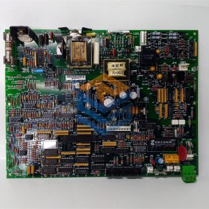
Description
SPECIFICATIONS
Part Number: IS200TVBAH2A
Manufacturer: General Electric
Country of Manufacture: United States (USA)
Series: Mark VI
Function: Terminal Board
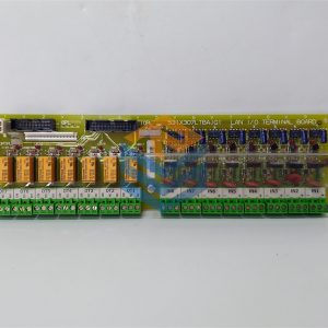
IS200TVBAH2A is a Vibration Input Terminal Board and is part of the GE Speedtronic Mark VIe gas turbine control system. The PVIB / YVIB I/O pack uses the Vibration Input (TVBA) terminal board as a signal interface board. Seismic (velocity), Proximitors, Velomitors, and accelerometer-type probes can all directly connect with the TVBA. For each input signal, the terminal board offers electromagnetic interface (EMI) protection and signal suppression. To enable open circuit identification, signals are additionally coupled to a pull-up bias. Through a 37-pin connector, the signals are sent to the I/O packs.
IS200TVBAH2A Functional Description
You can utilize the component for simplex or TMR applications. Three I/O packs are fanning the signal using TMR applications. The TVBA contains buffered outputs to additional connectors beyond the conventional 37-pin connection. This feature enables the Bently Nevada 3500 monitoring system to be powered via specific 9 and 25 pin connectors. This feature also includes a bayonet nut connection (BNC) connection for each channel to feed other third-party monitoring apparatus. Mark RKPS power supply are not used by VIe/VIeS control systems.
There is no external source of -28 V electricity; power is acquired from sourced +28 V power supplies.
The module features three detachable daughterboards to convert +28 to -28 as a result. All negative power used by the TVBA comes from these WNPS (negative power supply) boards.
IS200TVBAH2A Installation
Installation 14 sensor inputs that are wired directly to two I/O terminal blocks are accepted by the TVBA. Each block has 24 terminals that may accommodate wires up to #12 AWG and are secured with two screws. Each terminal block is close to a shield termination attachment point.
Input Channels 1 through 8:
Support for Proximitors, Seismics, Accelerometers (only channel 1, 2, and 3), and Velomitors.
Current-limited -24 V power supply per channel. JPxA jumper for configuring the open circuit check support and 3 mA constant current feed for Velomitors.
JPxB jumper for configuring the JA1 and JB1 outputs for the Bently Nevada 3500 rack. JPxC jumper for configuring PR0xL as Open for true
Input Channels 9 through 12:
Only Proximitors sensors are supported.
Each channel has a current-limited -24 V power supply.
Jumper setup is not allowed.
Input Channel 13:
Proximitors or Keyphasor proximity sensors are supported on Input Channel 13.
Each channel has a current-limited -24 V power supply, and jumper configurations are not allowed.
-28 V power supply board, WNPS:
Changes +28 V from PVIB/YVIB to -28 V for the outputs’ current limits of -24 V.
Independent +28 V inputs and a shared -28 V bus for all three WNPSs
One WNPS per PVIB/YVIB
Operation
14 sensor connections are supported by the TVBA:

IS200TVBAH2ACC
All prices listed on the official website are subject to confirmation by contact: Wu Jiedong (manager).
Our product: brand new original packaging
Our warranty: All new or repaired parts have a 12 month warranty period beginning
Our payment: 100% telegraphic transfer of inventory items before shipment, conditions can be proposed!
If you have any downtime spare parts that you cannot find, please feel free to call or use email to contact me. If there are issues that the product cannot solve, please contact me. Product prices can be negotiated. Please do not consider contacting me!


