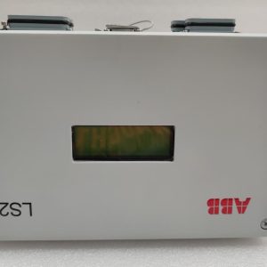
Description
General Information
Product ID:3BDH001010R0002
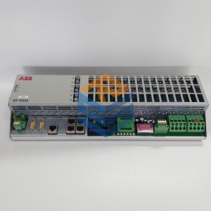
ABB Type Designation:CI 930F
Catalog Description:CI 930F PROFIBUS DP Master Module
Long Description:CI 930F PROFIBUS DP Master Module
Categories
Products » Control System Products » Control & Communication » AC 900F » AC 900F – Communication Modules » CI 930F PROFIBUS DP Master Module
Additional Information
Medium Description:PROFIBUS Master module for
DP-V0/V1, 12 MBit/s. Supports PROFIBUS line redundancy
Two D-Sub terminals (9-pole), one each for line A/B. Software version 2013 or higher is mandatory.
Use with AC 900F
Technical Information:DP-V0/V1, 12 MBit/s. Supports PROFIBUS line redundancy
Two D-Sub terminals (9-pole), one each for line A/B. Software version 2013 or higher is mandatory.
White housing
Product Type:Communication_ Module
Dimensions
Product Net Depth / Length:75 mm
Product Net Height:152 mm
Product Net Width:28 mm
Product Net Weight:0.15 kg
Deeply understand and analyze the process conditions and control requirements of the controlled object
The controlled object is the controlled mechanical, electrical equipment, production line or production process.
Control requirements mainly refer to the basic mode of control, actions to be completed, composition of automatic working cycle, necessary protection and interlocking, etc. For more complex control systems, the control task can also be divided into several independent parts, which can reduce complexity to simplicity and is conducive to programming and debugging.
Identify I/O devices
According to the functional requirements of the controlled object for the PLC control system, determine the user input and output equipment required by the system. Common input devices include buttons, selector switches, travel switches, sensors, etc. Common output devices include relays, contactors, indicator lights, solenoid valves, etc.
Select the appropriate PLC type
According to the determined user I/O equipment, count the number of input signals and output signals required, and select the appropriate PLC type, including the selection of model, capacity, I/O module, power module, etc.
Assign I/O points
Assign input and output points of PLC, prepare input/output distribution table or draw wiring diagram of input/output terminals. Then nine can carry out PLC program design, control cabinet or operation console design and on-site construction.
Design application system ladder program
According to the working function chart or state flow chart, the ladder diagram is designed, that is, programming. This step is the core work of the whole application system design, and it is also a difficult step. To design the ladder diagram well, you must first be familiar with the control requirements, and at the same time have some practical experience in electrical design.
All prices listed on the official website are subject to confirmation by contact: Wu Jiedong (manager).
Our product: brand new original packaging
Our warranty: All new or repaired parts have a 12 month warranty period beginning
Our payment: 100% telegraphic transfer of inventory items before shipment, conditions can be proposed!
If you have any downtime spare parts that you cannot find, please feel free to call or use email to contact me. If there are issues that the product cannot solve, please contact me. Product prices can be negotiated. Please do not consider contacting me!


