Description
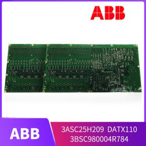
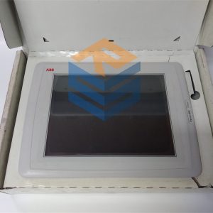
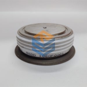
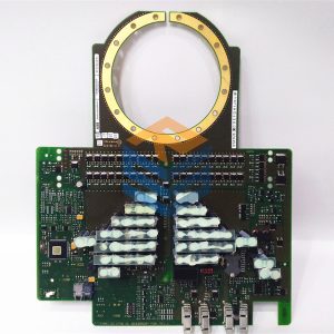
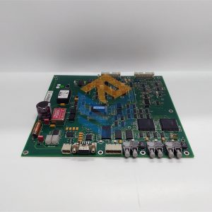
Zhengda commitment: SPBRC400
1. Guarantee new and original import
2. Ensure punctual delivery
3. Ensure after-sales service quality
Part Number: SPBRC400
Availability: In Stock
Estimated Lead Time: Usually Ships in1 – 3 Working Days
Shipping Weight: 4.5 Kg
After all programs are executed, the output processing stage will be entered. In this stage, the PLC transfers the output-related status (output relay status) in the output image register to the output latch and outputs it in a certain way to drive the external load.
Therefore, in a scan cycle, the PLC only samples the input state at the input sampling stage. When the PLC enters the program execution stage, the input end will be blocked, and the input status will not be resampled until the input sampling stage of the next scan cycle. This method is called centralized sampling, that is, sampling the input state for a period of time in a scanning cycle.
If the output result is assigned multiple times in the user program, the last time is valid. In a scan cycle, the output state is output from the output image register and the output interface is refreshed only at the output refresh stage. In other stages, the output state is always saved in the output image register. This method is called centralized output.
For small PLCs, the number of I/O points is small and the user program is short. Generally, centralized sampling and centralized output are adopted. Although the response speed of the system is reduced to a certain extent, the PLC is isolated from the external input/output equipment for most of the time, fundamentally improving the anti-interference ability of the system and enhancing the reliability of the system.
For large and medium-sized PLCs, there are many I/O points, strong control functions, and long user programs. In order to improve the system response speed, a variety of methods can be adopted, such as regular sampling, regular output, or interrupt input, output, and intelligent I/O interface.
From the above analysis, it can be seen that when the input signal of PLC changes and the PLC output responds to the input change, it takes a period of time. This phenomenon is called PLC input/output response lag. For general industrial control, this lag is completely allowed. It should be noted that this response delay is not only caused by the PLC scanning mode, but also by the input delay caused by the filtering link of the PLC input interface, and the output delay caused by the action time of the driving device in the output interface, and also related to the program design. The lag time is a parameter that should be paid attention to when designing the PLC application system.

SPBRC300

SPBRC300

SPBRC400
All prices listed on the official website are subject to confirmation by contact: Wu Jiedong (manager).
Our product: brand new original packaging
Our warranty: All new or repaired parts have a 12 month warranty period beginning
Our payment: 100% telegraphic transfer of inventory items before shipment, conditions can be proposed!
If you have any downtime spare parts that you cannot find, please feel free to call or use email to contact me. If there are issues that the product cannot solve, please contact me. Product prices can be negotiated. Please do not consider contacting me!


