Description
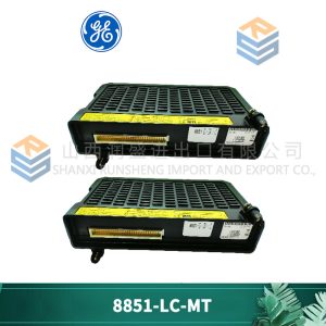
SafetyNet IO Modules
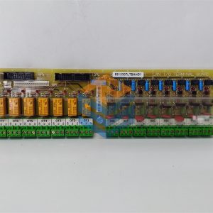
SafetyNet IO Modules interface to safety system field wiring via Field Terminals.. The IO Modules and the Field Terminals mount on Carriers that provide mechanical support, but also connect the internal communication bus and power supply connections to the Modules.. The IO Modules are certified as suitable for use in SIL 2 safety-related applications..
•Certification
The SafetyNet IO Modules are certified for use in safety-related applications up to and including SIL 2.. The SafetyNet System achieves this certification with a 1oo1D architecture.. The SafetyNet IO Modules have been designed specifically for safety-related applications and are certified on the basis of the excellence of their design.. The certification does not depend on “proven in use” data..
•Diagnostics
The IO Modules perform comprehensive internal diagnostic tests as an essential part of ensuring that the IO can carry out the required safety function.. If the SafetyNet IO Module’s internal diagnostics detect a fault that would prevent the SafetyNet System from carrying out its safety function,
then it will initiate a controlled shutdown.. A controlled shutdown has two objectives – firstly, to ensure that the IO Module enters its failsafe mode; and secondly, to record sufficient data to allow the reason for the shutdown to be determined.. If a SafetyNet Module enters a controlled shutdown, then
all IO channels are deactivated: input channels are not scanned; and output channels are de-energized..
•Bussed Field Power
The Bussed Field Power (BFP) connectors on the rear of IO Module Carriers provide the power connections for field instruments wired to the IO Modules.. For the SafetyNet System, BFP must be 24 VDC and supplied by MTL’s 8914-PS-AC units.. These power supplies may be used in redundant pairs, if required..
•Live Maintenance
SafetyNet IO Modules can be removed and replaced in a Class 1, Division 2 or Zone 2 hazardous area – once the relevant Bussed Field Power (BFP) connection has been isolated using an appropriate hazardous area switch (such as the MTL951).. Removing
and replacing the Modules does not interrupt the operation of the other parts of the node.. If a Module is replaced by another Module of identically the same type, then no
intervention is required for the System to begin operating normally once the Bussed Field Power is restored..
•Line Fault Monitoring
In addition to the comprehensive internal diagnostics the SafetyNet IO Modules can monitor field wiring for line faults..
Data from SafetyNet IO Modules can be time stamped and stored by the SafetyNet Controller before being downloaded to the PAC8000 SOE Data Retrieval Client or a 3rd party historian package.. SafetyNet IO Module data
is time stamped with a resolution of better than 200ms..
•Failsafe Mode
IO Modules will enter Failsafe Mode from the Running State either due to loss of communications with the Controller or because the module has received an instruction from the
Controller to enter the Failsafe State.. In this state:
– The Red Fault LED is lit
– The IO Module is flagged as unhealthy to the Controller
– All Railbus Write requests are rejected, except instructions to Reset or to exit the Failsafe State
– Inputs and HART data are read – Outputs are de-energized
– Background diagnostics continue and if a failure is detected, the module will enter Controlled Shutdown
•Controlled Shutdown
A Controlled Shutdown is carried out if a fault is detected in the Module.. In this state it can communicate the reason for shutdown..
•LEDs
A number of LEDs are provided on each IO Module to provide visual indication of the status of the Module, its channels and its power supply..
•Module ‘Fault’ LED (red)
– On – Failsafe
– Off – Normal operation Flashing (equal:mark space ratio) – Cold start in process, will flash until communication is established with SafetyNet Controller..
– Blinking (On for a short period, then On for a longer period – morse code ‘a’) – Fault state after controlled shutdown
•Module ‘Power’ LED (green)
– On – Power OK
– Off – BFP or Railbus Power Failure
•Module ‘Channel’ LED’s (yellow)
All prices listed on the official website are subject to confirmation by contact: Wu Jiedong (manager).
Our product: brand new original packaging
Our warranty: All new or repaired parts have a 12 month warranty period beginning
Our payment: 100% telegraphic transfer of inventory items before shipment, conditions can be proposed!
If you have any downtime spare parts that you cannot find, please feel free to call or use email to contact me. If there are issues that the product cannot solve, please contact me. Product prices can be negotiated. Please do not consider contacting me!


