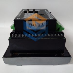
Description
The VMIVME-7455 is designed to interface with VMIC’s PC/AT family of CPUproducts. A 6U single-slot VMEbus passive board, that contains a 24x Multisessionphoto CD-ROM drive, compatible with CD-I, Video CD, Enhanced CD, and CDPLUS. CPU boards connect to the VMIVME-7455 by way of the P2 connector on theVMEbus backplane. The VMIVME-7455 is also compatible with VMIC’sVMIVME-7452 Single-Slot VMEbus Floppy/Hard Disk Module with Flash Memory.A diagram of the VMIVME-7455 is shown in Figure 1 on page 6.Three separate procedures are outlined in this installation guide:1. Installation of the VMIVME-7455 with the VMIVME-7589, or -7589A CPU.2. Installation of the VMIVME-7455 with the VMIVME-7591, -7592, or the -7695*.3. Installation of the VMIVME-7455 with the VMIVME-7696 CPU
The VMIVME-7455 receives and passes IDE signals by way of the P2 connector,routed through the backplane from the following CPUs: VMIVME-7589 andVMIVME-7589A. To utilize the P2 configuration, a backplane which supports I/ Ocabling from the rear must be used, along with a 64-conductor cable assembly (VMICModel Number VMIVME-VMXC-3), see Figure 4 below. Figure 5 on page 10 is anillustration of the installation. The cable is supplied with the VMIVME-7455. Figure 4shows the cable used with the VMIVME-7589, or the VMIVME-7589A.When installing the VMIVME-7589, or the -7589A with the VMIVME-7455, and theoptional VMIVME-7452, the boards must be installed in consecutive slots. Undercertain conditions the system may require a longer cable, this cable is available as(VMIC Model Number VMIVME-VMXC-7), see Figure 7 on page 12.The P2 connection to the VMIVME-7589, or the VMIVME-7589A involves thefollowing board configuration:1. Ensure that jumper J12 on the VMIVME-7589, or the VMIVME-7589A is2. Insert the CPU into the desired slot.3. Insert the VMIVME-7455 into the desired slot.4. Install the 64-conductor cable assembly onto the rear of the backplane. The cableFigure 4 64-Conductor Cable Assembly (Model No. VMIVME-VMXC-3)Artisan Technology Group – Quality Instrumentation … Guaranteed | (888) 88-SOURCE | www.artisantg.comInstallation of the VMIVME-7455 with the VMIVME-7589, or the VMIVME-7589Aconfigured to route the signals to the P2 connector. A jumper shunt should beinstalled on pins 2 and 3, to utilize the P2 connector. Refer to the ProductManuals for the jumper configuration.must be connected to the rear I/O shrouded P2 connectors of both slots. Oneoccupied by the VMIVME-7589, or the VMIVME-7589A and the other connectedto the VMIVME-7455 P2 connector.
1SBP260100R1001
1SBP260054R1001
1SBP260052R1001
1SBP260051R1001
1SBP260021R1001
1SBP260014R1001
1SBP260012R2002
1SBP260012R1001
1SBP260011R1001
1SBP260010R1001
1SBP260001R1001
GJR5253300R3161
GJR5251400R0101
GJR5251300R2171
GJR5251300R0161
GJR5251300R0101
All prices listed on the official website are subject to confirmation by contact: Wu Jiedong (manager).
Our product: brand new original packaging
Our warranty: All new or repaired parts have a 12 month warranty period beginning
Our payment: 100% telegraphic transfer of inventory items before shipment, conditions can be proposed!
If you have any downtime spare parts that you cannot find, please feel free to call or use email to contact me. If there are issues that the product cannot solve, please contact me. Product prices can be negotiated. Please do not consider contacting me!


