Description
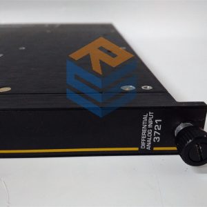
TRICONEX 2841
A controller contains three MPs. Each MP controls a separate channel and operatesin parallel with the other two MPs.A dedicated I⁄O control processor on each MP manages the data exchangedbetween the MP and the I⁄O modules. A triplicated I⁄O bus, located on thebaseplates, extends from one column of I⁄O modules to another column of I⁄Omodules using I⁄O bus cables.As each input module is polled, the appropriate channel of the I⁄O bus transmitsnew input data to its MP. The input data is assembled into a table in the MP and isstored in memory for use in the voting process.The individual input table in each MP is transferred to its neighboring MP over theTriBus. After this transfer, voting takes place. The TriBus uses a programmabledevice with direct memory access to synchronize, transmit, and compare dataamong the three MPs.If a disagreement occurs, the signal value found in two of three tables prevails, andthe third table is corrected accordingly. One-time differences which result fromsample timing variations are distinguished from a pattern of differing data. EachMP maintains data about necessary corrections in local memory. Any disparity isflagged and used at the end of the scan by the built-in fault analyzer routines todetermine whether a fault exists on a particular module.The MPs send corrected data to the application. The 32-bit MP executes theapplication in parallel with the neighboring MPs and generates a table of outputvalues that are based on the table of input values according to user-definedrules.The I⁄O control processor on each MP manages the transmission of outputdata to the output modules by means of the I⁄O bus.
Using the table of output values, the I⁄O control processor generates smaller tables,each corresponding to an individual output module. Each small table is transmittedto the appropriate channel of the corresponding output module over the I⁄O bus. Forexample, MP A transmits the appropriate table to channel A of each output moduleover I⁄O bus A. The transmittal of output data has priority over the routine scanningof all I⁄O modules.Each MP provides a 16-megabyte DRAM for the user-written application,sequence-of-events (SOE) and I⁄O data, diagnostics, and communication buffers.(For more information about SOE, see the Sequence of Events Recorder User’sManual.) The application is stored in flash EPROM and loaded in DRAM forexecution. The MPs receive power from redundant 24 volts DC power sources. Ifan external power failure occurs, all critical retentive data is stored in NVRAM. Afailure of one power source does not affect controller performance. If the controllerloses power, the application and all critical data are retained indefinitely.
All prices listed on the official website are subject to confirmation by contact: Wu Jiedong (manager).
Our product: brand new original packaging
Our warranty: All new or repaired parts have a 12 month warranty period beginning
Our payment: 100% telegraphic transfer of inventory items before shipment, conditions can be proposed!
If you have any downtime spare parts that you cannot find, please feel free to call or use email to contact me. If there are issues that the product cannot solve, please contact me. Product prices can be negotiated. Please do not consider contacting me!


